Simulation of the Gas Flow in Siegbahn and Holweck Molecular Drag Pumps
Introduction
A turbo molecular pump is used whenever a very low pressure must be maintained in a chamber. A turbo pump consists of multiple turbo stages where each stage contains a rotor and a stator.
Modern turbo pumps combine turbo stages and drag stages. A drag stage uses the principle of molecular drag to pump gas. There are two variants of drag stages: Siegbahn stages and Holweck stages both named after their inventors.
PI-DSMC can be used to simulate the flow in turbo stages, Siegbahn stages and Holweck stages.
The performance of a drag pump or a turbo pump is measured by the compression which is the ratio between the pressure at the inlet and the pressure at the outlet. The more stages a pump contains, the higher the compression ratio.
The compression is constant in the free molecular flow regime and decreases with increasing pressure at the inlet in the transition flow regime.
A second quantity that measures the performance is the pumping speed. The pumping speed is defined as the amount of gas that can be pumped per unit time. Also the pumping speed depends on the flow regime.
Both the compression and the pumping speed can be applied to a single stage - turbo, Siegbahn and Holweck - or to multiple stages.
The compression and the pumping speed can be simulated using PI-DSMC. A simulation is more flexible and cheaper than an experiment because it is not necessary to build a prototype and gas supply system.
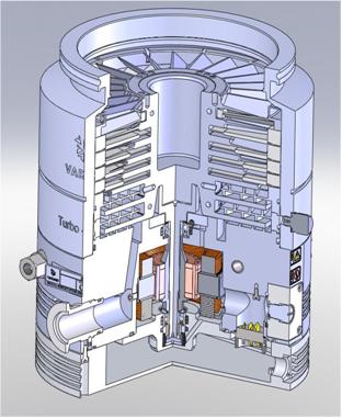
The left image below shows the interior of a modern turbo pump with the inlet at the top. The pump consists of 5 turbo stages and 5 Siegbahn stages.
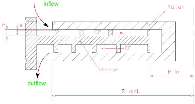
The image below shows a cross section of a Siegbahn stage. The rotor is basically a plain disk while the stator contains spiral ribs forming channels between them. The rotating disk drives the gas through the channels. The spacing between rotor and stator has a significant impact on the performance of the stage.
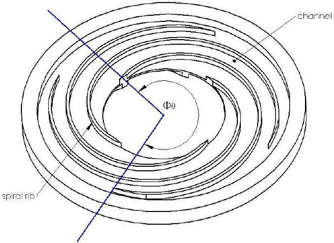
The image below shows a stator with ribs and channels. Obviously, the performance of the stage depends on the shape of the channels.
Example - Siegbahn stage
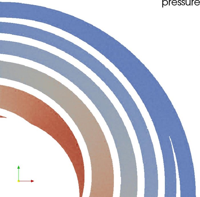
PI-DSMC was used to simulate the 3D gas flow in a Siegbahn stage with a 90 degree rotational symmetry. In order to determine the compression, the pressure at the inlet and the outlet is determined from the simulation.
The two images below shows the radial pressure profile. The direction of rotation of the rotor is such that the gas is driven towards the center. The gas inlet is at the outer radius and the outlet is in the center.
In the simulation, the inlet is closed by a wall and the outlet is a gas interface. The simulation is conducted until the number of simulated molecules reaches equilibrium.
In the steady state the pressure at the outlet can be determined.

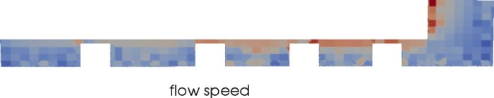
The image below shows the radial velocity profile. The flow speed is high near the rotor (top edge) and low near the stator.
Example - Holweck stage
The discussion above also applies to the Holweck stage. PI-DSMC was used to determine the compression and the pumping speed using a standard geometry.